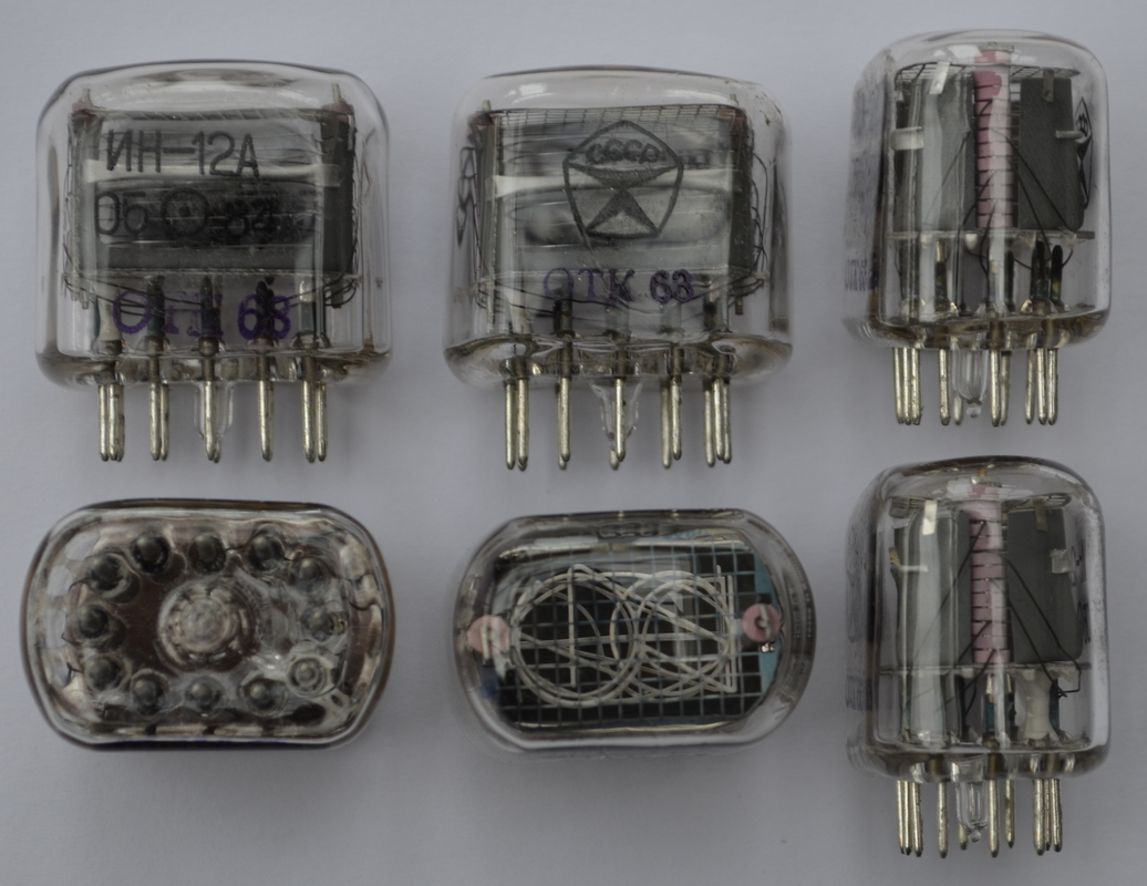
I recently purchased a set of 12 IN-12A (ИН-12А) nixie tubes from Russia. I was eager to try them out and make sure they survived the trip. For this I built a very basic high voltage power supply to fire them up, and then got a bit carried away!
This article concerns the use of a relatively high voltage supply. Stay safe when working with high voltage, and do not proceed until you are comfortable with the required precautions. Any attempt to replicate these experiments is at your own risk!
Nixie Tubes
You’ve no doubt seen nixie tubes by now. For the uninitiated, they were a form of numeric display used before the advent of 7-segment LED displays. A glass envelope encloses an mostly neon atmosphere, along with cathodes in the shape of numerals, and a anode grid. When a high voltage is applied between the anode and one of the cathodes, the numeral glows.
There has been something of a resurgence in their use, especially by makers. There are hundreds of nixie tube clocks out there, along with some other novel uses.
My nixies seem to be Soviet new-old-stock, produced in May of 1984. (I assume 05⊙84 is the date code.)
The Power Supply
Nixies are gas-discharge tubes, and consequently exhibit negative differential resistance. This wonderfully titled phenomenon means that in practical terms, we need a higher voltage to turn the tube on that we do to run it. The turn on voltage is called the “striking voltage”. Once the tube is “struck” a sustaining voltage keeps the discharge going.
For the IN12A, the striking voltage is ≤ 170 V, while the sustaining voltage is ≥ 120 V. The sustaining current is ≤ 2.5 mA. The challenge here then is not the amount of power required, but the high voltages involved.
The usual approach is to build a boost converter to take around 12 V and step it up to the required high voltage. Unfortunately I didn’t have the appropriate parts to hand. The mains however is a more than capable source of these high voltages!
An isolation transformer would be an ideal safe place to start this project, but unfortunately I don’t own one. What I did have to hand though were a pair of low power 12 V transformers.
Connecting the secondaries together and putting 240 V on one primary got me about 200 V at the other primary. This was expected, and is a result of a mixture of losses between the two transformers. The lower voltage is actually ideal for this project.
A single diode half wave rectifier, a high voltage electrolytic capacitor, an a bleeder resistor were all that was required to obtain a 210V DC rail. The supply was placed inside the plastic enclosure of a 40A isolator. As an additional safety feature I set this up so that I could short out the supply while it was not switched on.
Ballast Resistor
To keep the nixie tube from drawing excessive current after striking, a ballast resistor is needed to limit the current. The calculation of this resistor is much like that for an LED.
$$ \frac{V_\text{supply} - V_\text{sustain}}{I_\text{sustain}} = R_\text{ballast} $$
In this case the ballast resistor can be calculated as follows:
$$ \frac{210 \text{V} - 120\text{V} }{2.5 \text{mA}} = 36 \text{k}\Omega $$
The First Illumination
Keeping a close eye on the current and voltage, the supply was turned on. After a second the nixie popped into life and I was presented with a brilliant orange number 4.
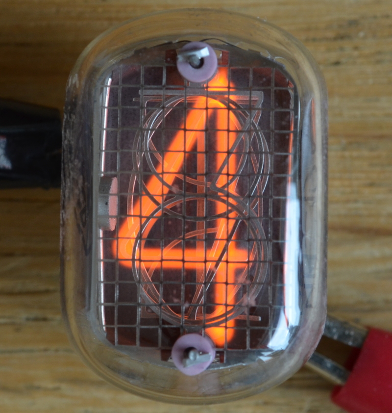
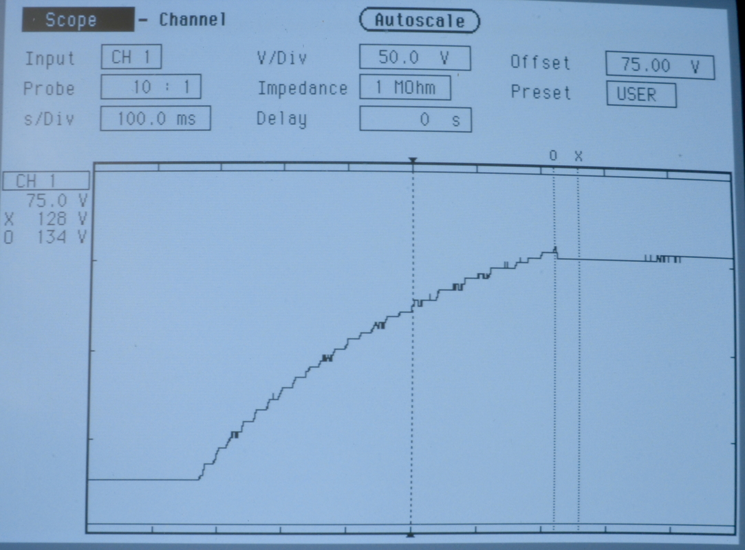
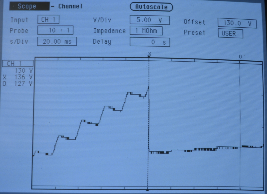
Some later testing revealed that \(V_\text{sustain}\) was actually 134 V. I ended up using a 33 kΩ resistor. This gave an operating current of 1.75 mA, and a more than bright enough digit to read clearly in bright light.
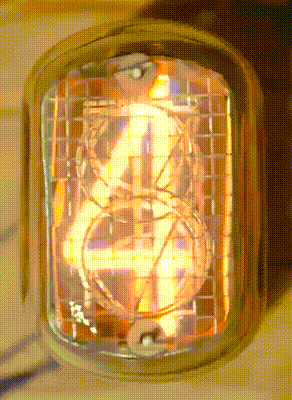
Looping Digits
After getting a single digit to light up, I was eager to start controlling the tube. A simple demonstration would be to cycle through the digits.
I built up a simple 4017 counter. Unfortunately I could only find 4 transistors capable of handling the high \(V_\text{CE}\) required, so I only got to loop 4 digits. I’m still very pleased with the result so far!
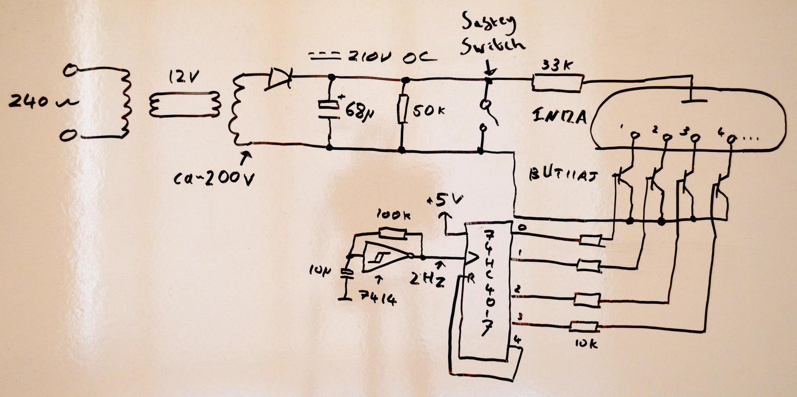
Schematic
Please excuse the WhiteboardCAD schematic. It’s not 100% complete, but it gets the point across!
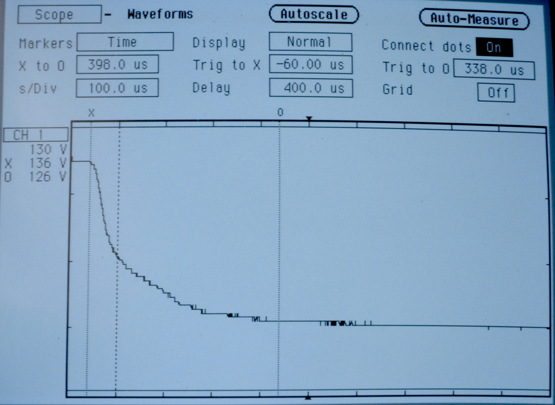
Power Up Characteristics
I thought it would be interesting to see the power on characteristic of the tube on the scope. Note that you could blow up your scope if you’re not careful here!